copier jam
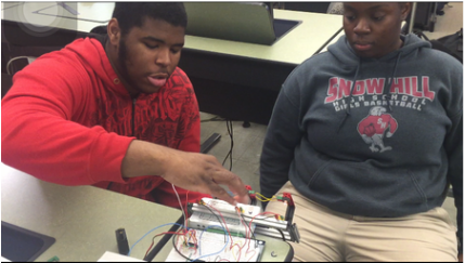
For this project, my partner and I were tasked with creating something that would simulate a copier jam.

|

|


part explanation
Resistors- Limit the amount of voltage throughout the circuit
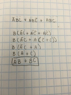
Combinational Logic Circuit- This is used to detect the paper jam. When light sensors that are beside each other can't sense light, the motor stops, the buzzer starts, and the LEDs light up. AB and BC represent the combination of lights that would set of the buzzer and stop the motor.
LED & Buzzer- They both come on when the jam is detected, but the buzzer can be shut off when the copier is reset and the LEDs stay lit until the jam is no longer present.
Flip Flops- They keep the buzzer on until the copier is reset, even when the jam is cleared.
